 |
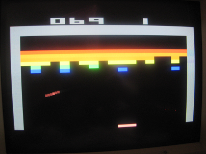 |
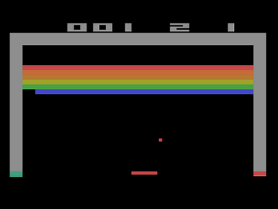
| Original Atari 2600 Breakout | FPGA Breakout |
|
|
| Original Atari 2600 Breakout | FPGA Breakout |
|
This project will attempt to recreate the famous Atari video game Breakout.
The project will be created using a Xilinx Virtex-II FPGA with the XUPVP2 development board and written in Verilog.
The game's graphics are generated on a VGA monitor using the results from a lab assignment that had us create
a 640x480 resolution VGA driver (just painted the screen a color). The pixels will have to be scaled up to create the standard large
pixel Atari graphics, but that shouldn't be too hard - I'll just mod the horizontal and vertical counters. Also a PS/2 keyboard
driver (also developed from a lab) will be used so that keyboard input can be used as the controller. Hopefully, time permitting,
I'll be able to work it out to interface to a real Atari joystick for the game.
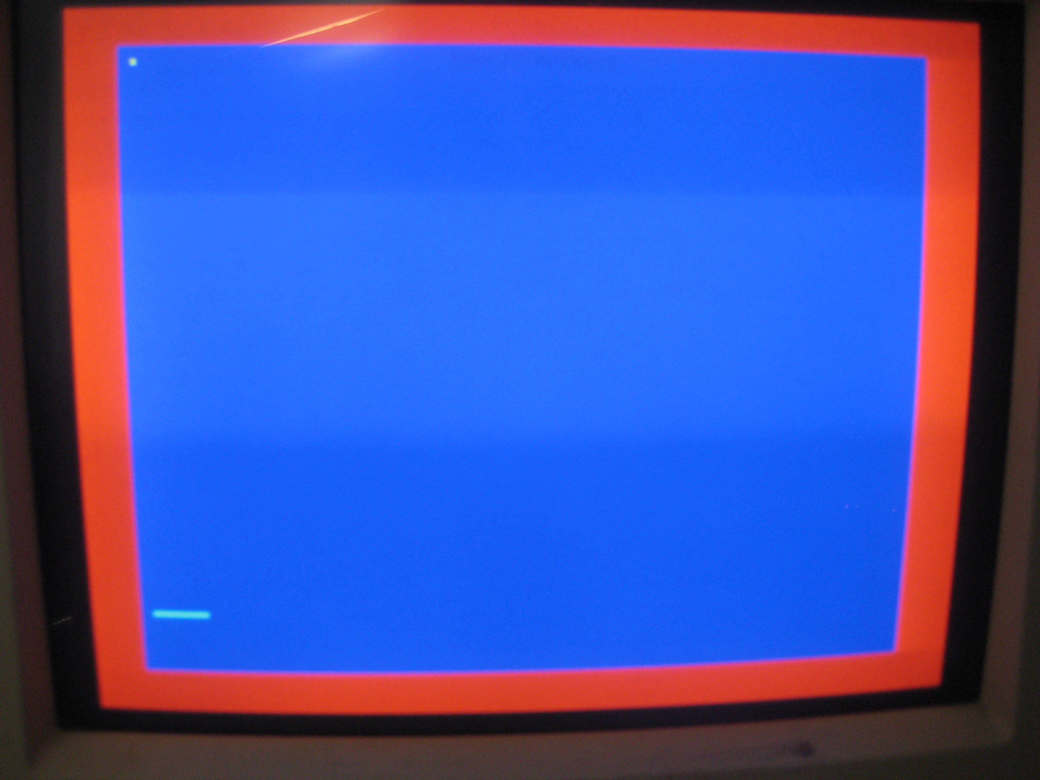
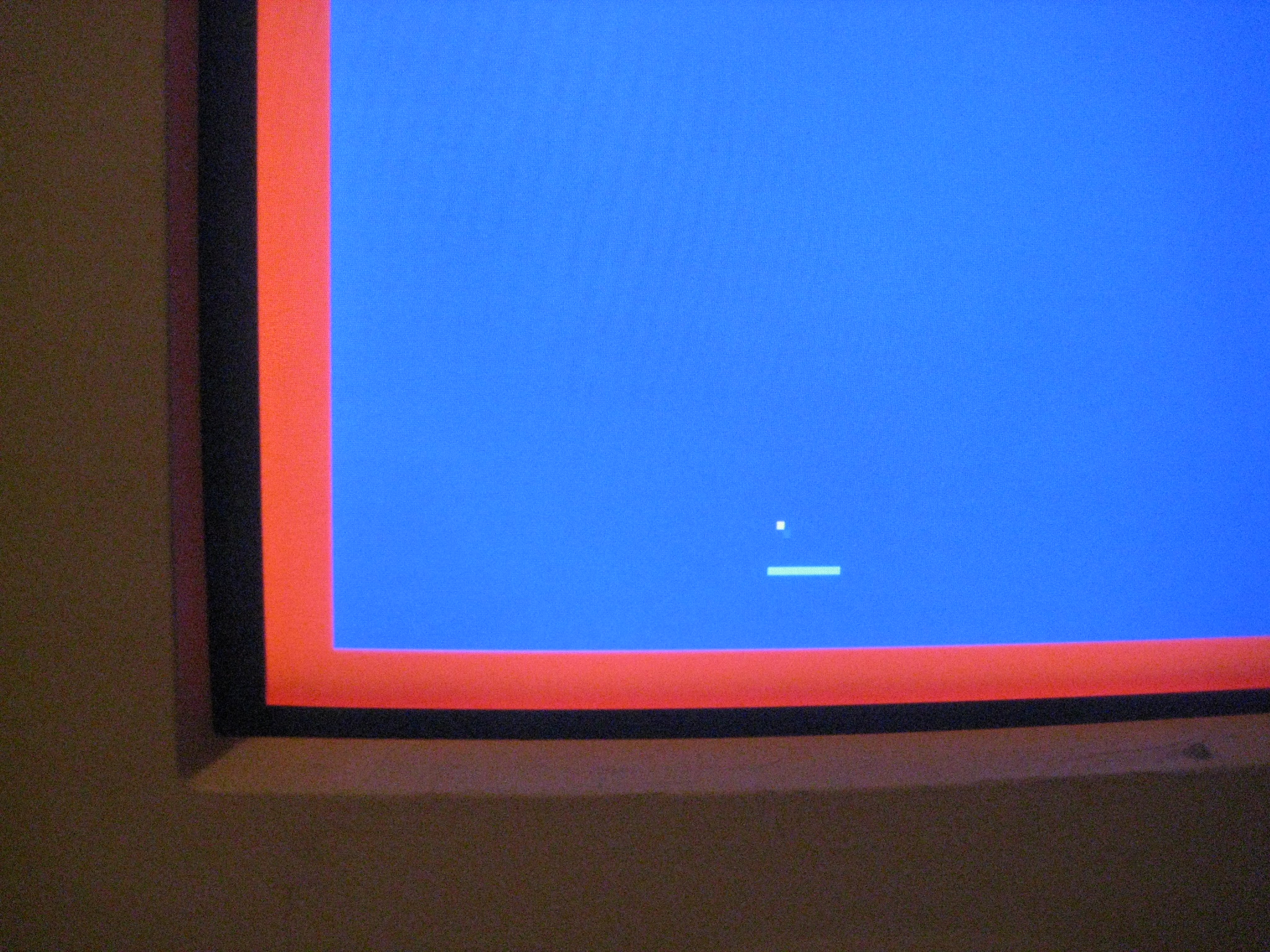
Starting off I decided to try some simple tasks: 1. Create a scaled up resolution - every pixel is quadrupled, so 1 pixel is 4x4 640x480 pixels. 2. Draw some objects at specific locations on the screen. 3. Make those objects moveable. Turns out it wasn't too hard to scale up the pixels and create some graphics. New counters (x,y) were generated from the original 640x480 VGA Horizontal and Vertical counters that were basically incremented every 4 pixels. So the new resolution becomes 160x120. Here's a pic: |
||||||||||||||||||||
|
||||||||||||||||||||
|
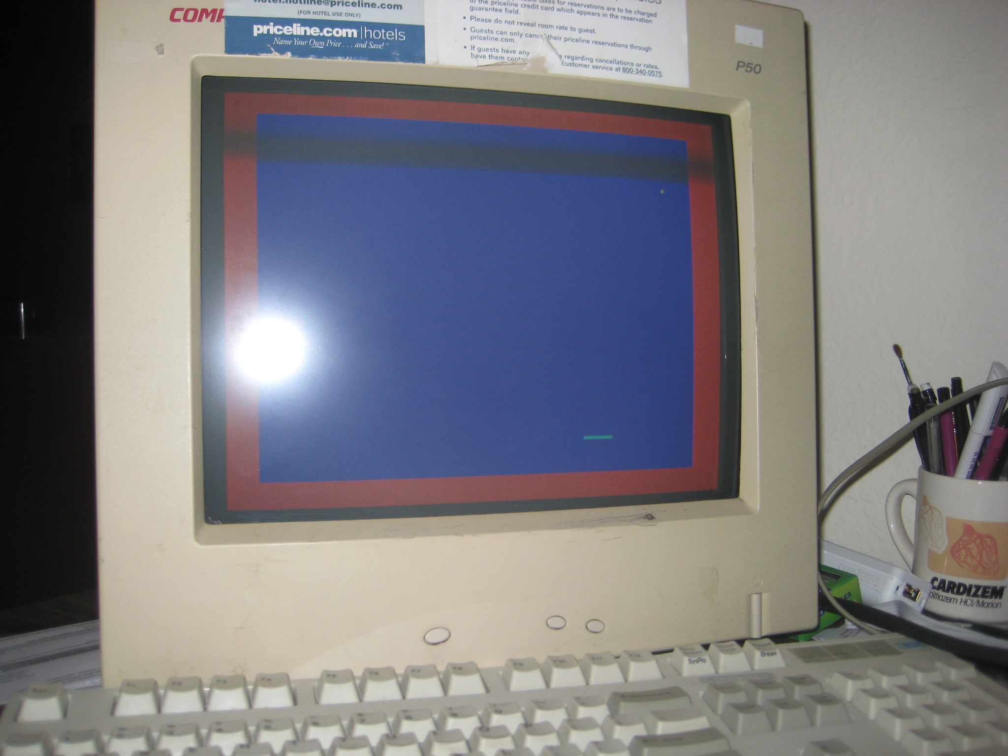
Now movement... I thought I'd basically make 2 counters, 1 for the paddle and 1 for the ball that would basically act as
delays so that each would be updated slower than the 25MHz VGA timing signals (refresh rate of 1 pixel). The paddle and ball would each have an X and Y
variable that would be updated at their counter delays. The paddle's position would be updated by keyboard input (y is constant) and
the ball would be updated and altered every "ballFrame" by movement through open space or if it hits a wall or the paddle.
So after a while, this came together quite simply.
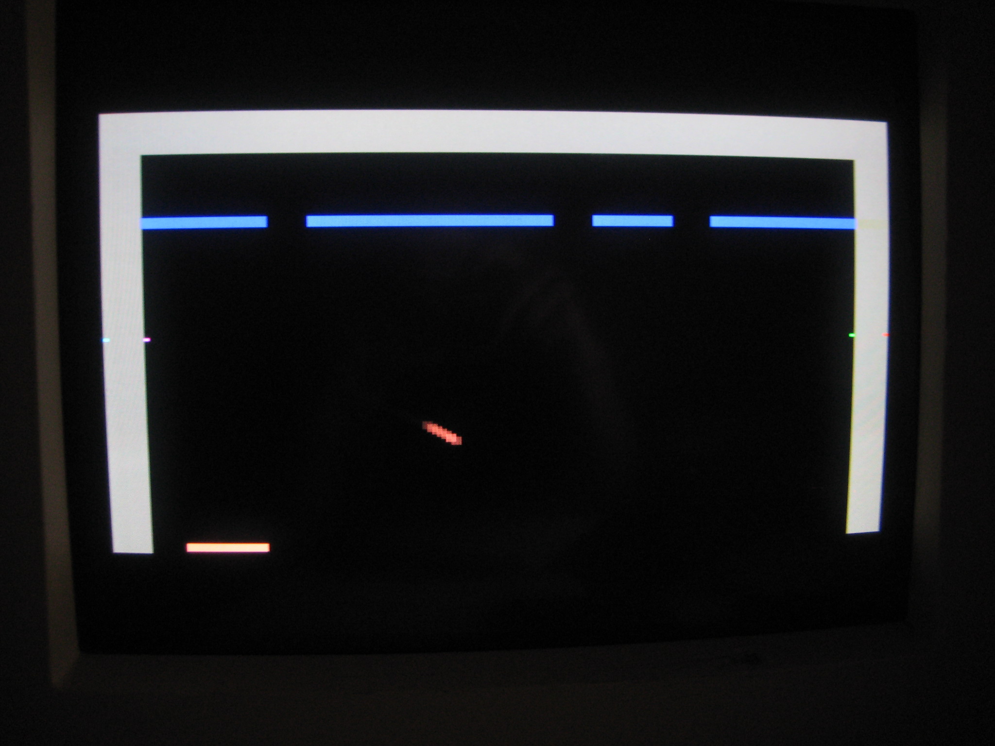
The paddle moves by pressing '1' (left) or '2' (right) on the keyboard, while the ball moves around with a 1/1 slope. It's trajectory alters if its position intersects with a wall or paddle edge... for example, if it its the top of the paddle, the Y-slope value inverts while the X-slope value remains unchanged... sending the ball moving back up. Check it out... |
||||||||||||||||||||
|
||||||||||||||||||||
|
||||||||||||||||||||
| And here's a video! Breakout Graphics - Take 1 | ||||||||||||||||||||
|
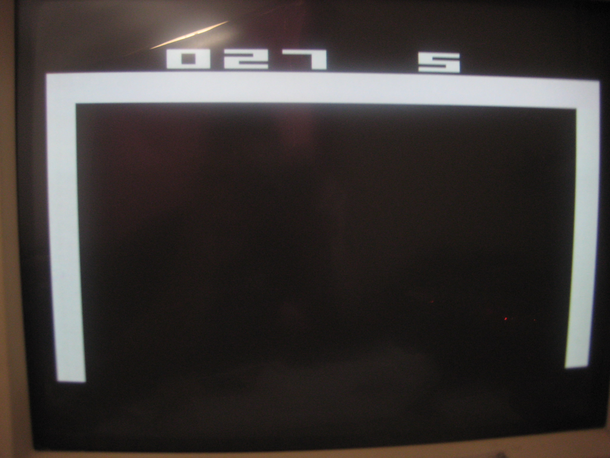
So after some time away doing other lab assignments I finally got back to working on the game. This time I decided to work on getting the VGA resolution set to the standard Atari resolution of 160x192 pixels. This is a quite odd resolution that doesn't really fit with other typical aspect ratios like 4:3 or 16:9. So after some quick analysis I realized that to convert my 640x480 view area into 160x192, I'd have to do the following:
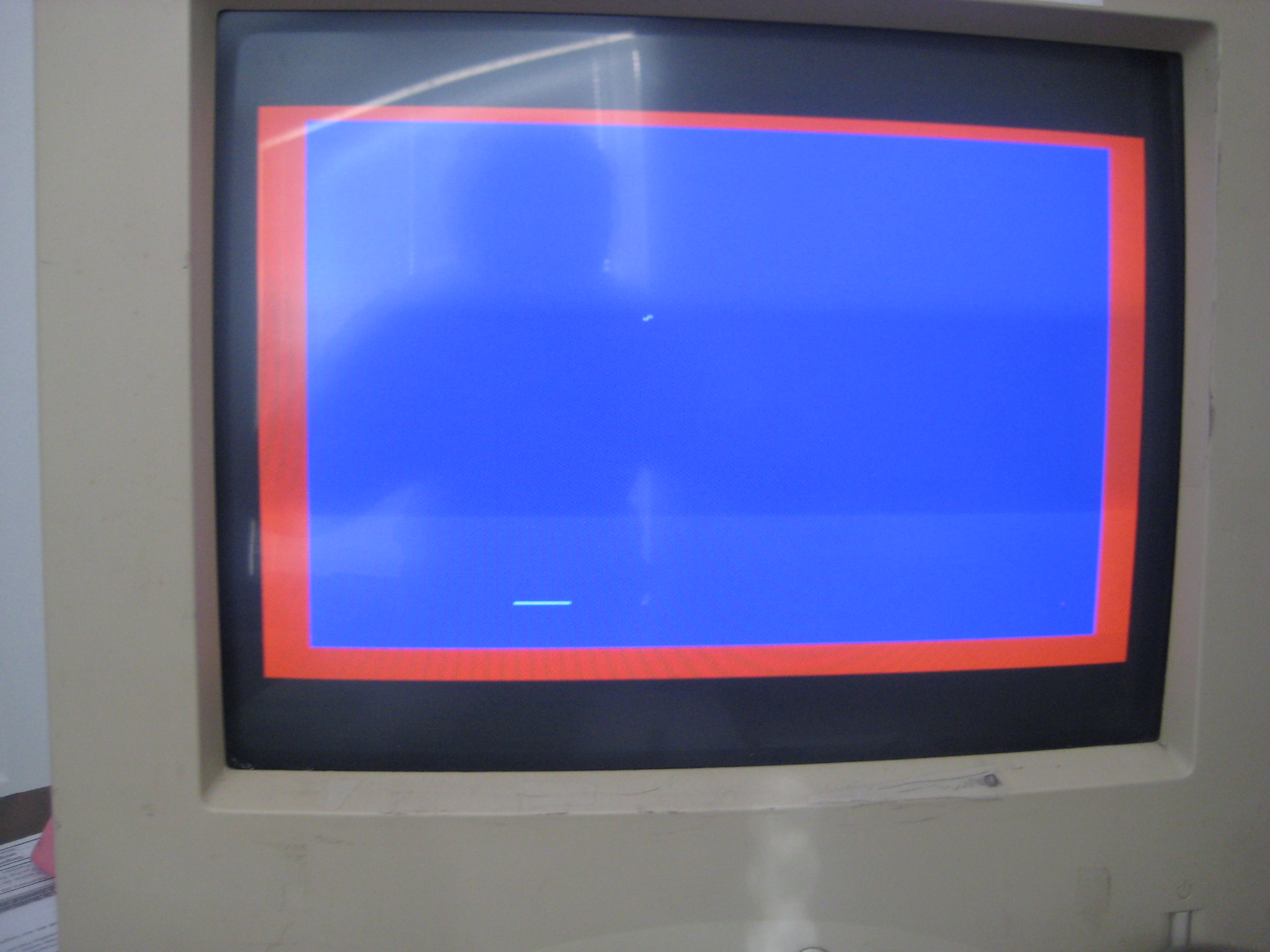
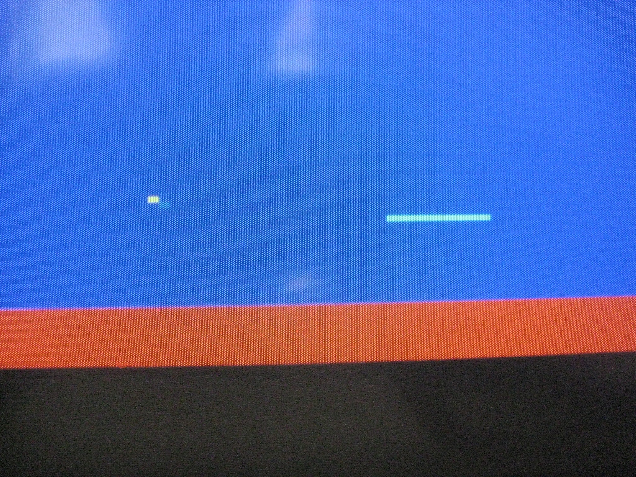
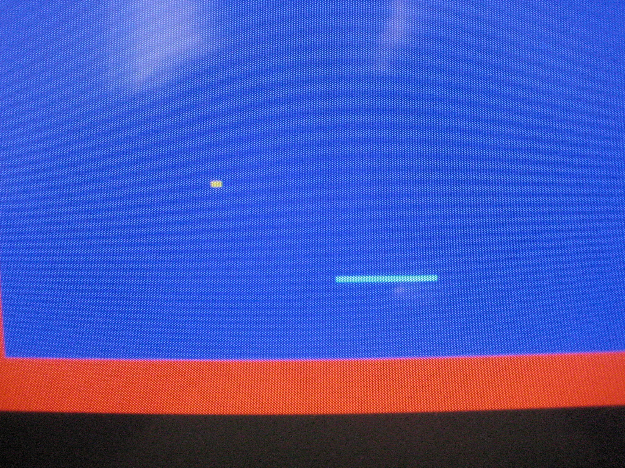
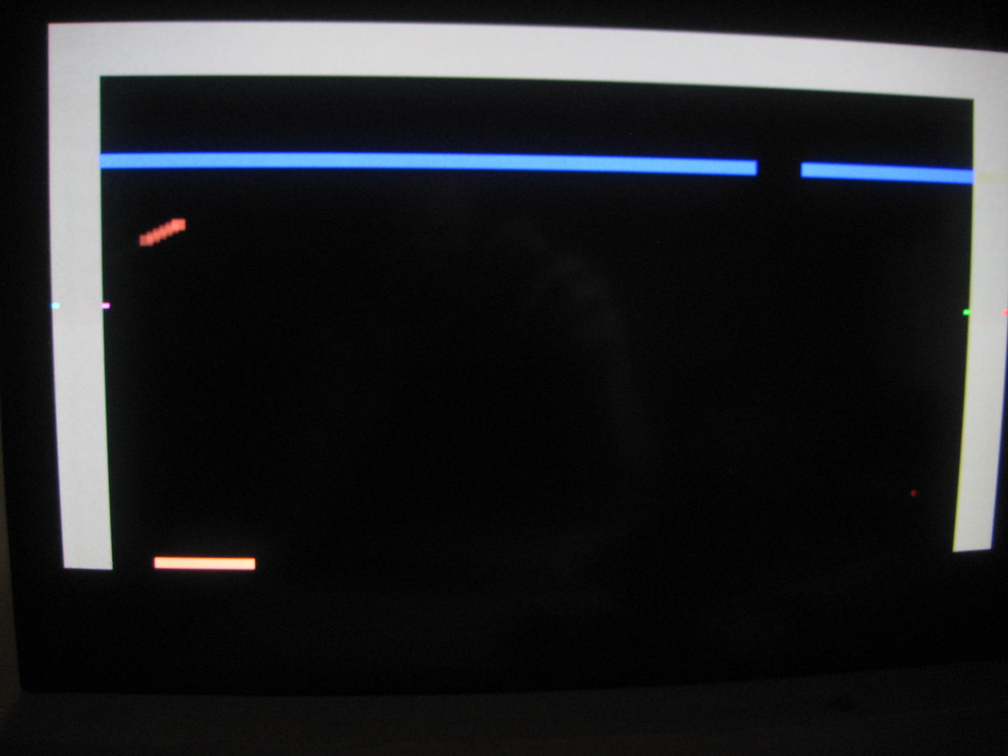
Applying these mods to the Pixel_X and Pixel_Y variables worked well. But I noticed that I had some misplaced pixels near the corners and edges of the display area. It took forever to figure out, but it turned out that it was because I was scaling the oringal horizontal and vertical counts (which range from 0 to 793 (Hor) and 0 to 521 (Vert) - includes active and blanking region) only in the active region (0 to 639 and 0 to 479). So what this did was make my 160x192 pixel x,y counters hold their values at 639 and 479 when the underlying counters were still incrementing. Basically, when at 639 and 479, my pixel counters remained 159 and 191 until the base counters reset back to zero... not good. The hold resulted in the pixel placement to be off (rotated over to the opposite screen edge, etc) because the graphics logic would continue to write color to the screen, even in the blanking region, which is a no-no in VGA. The blanking region always needs the RGB pins to be deasserted so that the video adapter can do internal processing, like sweep the electron beam back to the next line. Anyway, after making those tweaks, I finally was able to see a clean picture of the original bouncing ball and paddle, but this time in true Atari 2600 flat, blocky rectangular pixel resolution. |
||||||||||||||||||||
|
||||||||||||||||||||
|
||||||||||||||||||||
|
||||||||||||||||||||
| Here's a vid of the 160x192 res in action Breakout Graphics - Take 2 | ||||||||||||||||||||
|
The next goal was to work on building up the look and feel of the game to match the original. I basically took a printout screenshot of the original Breakout game, a ruler, and pencil and did some visual approximations for the size of the ball, walls, and paddle. After some trial and error, I was able to get the exact sizes of every object... at least they look right. Below is a list of the pixel dimensions for each object I came up with:
|
||||||||||||||||||||

|
||||||||||||||||||||
|
Moving right along... Now the hard stuff: brick collisions. So after thinking about a solution for this I came up with an idea to have a buffer that holds the state of each brick (active or destroyed). The buffer would be 108 bits (1 bit/brick) with a '1' indicating the brick is still on the screen and a '0' indicating it has been destroyed. This buffer would be checked to determine which bricks get drawn to the screen as well as if we should do some collision logic or not. I started working on 1 row of 18 bricks to try to get the basic functionality down. It took me about 3 days to get the collision detection logic down, it was kinda tricky logic, but I eventually got it working. It shouldn't be too hard to update this to include the other five rows... well, let's hope. |
||||||||||||||||||||
|
||||||||||||||||||||
|
||||||||||||||||||||
|
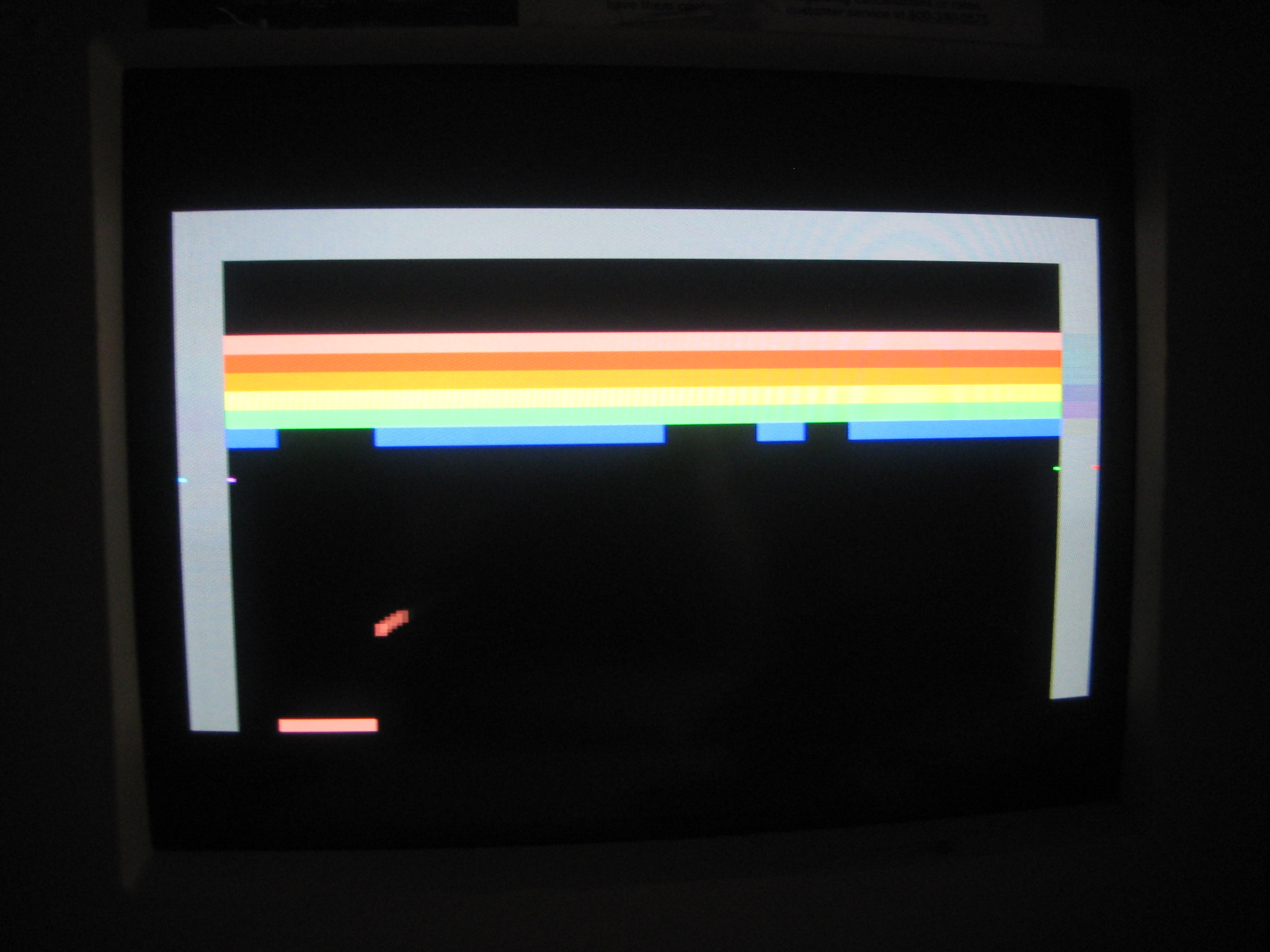
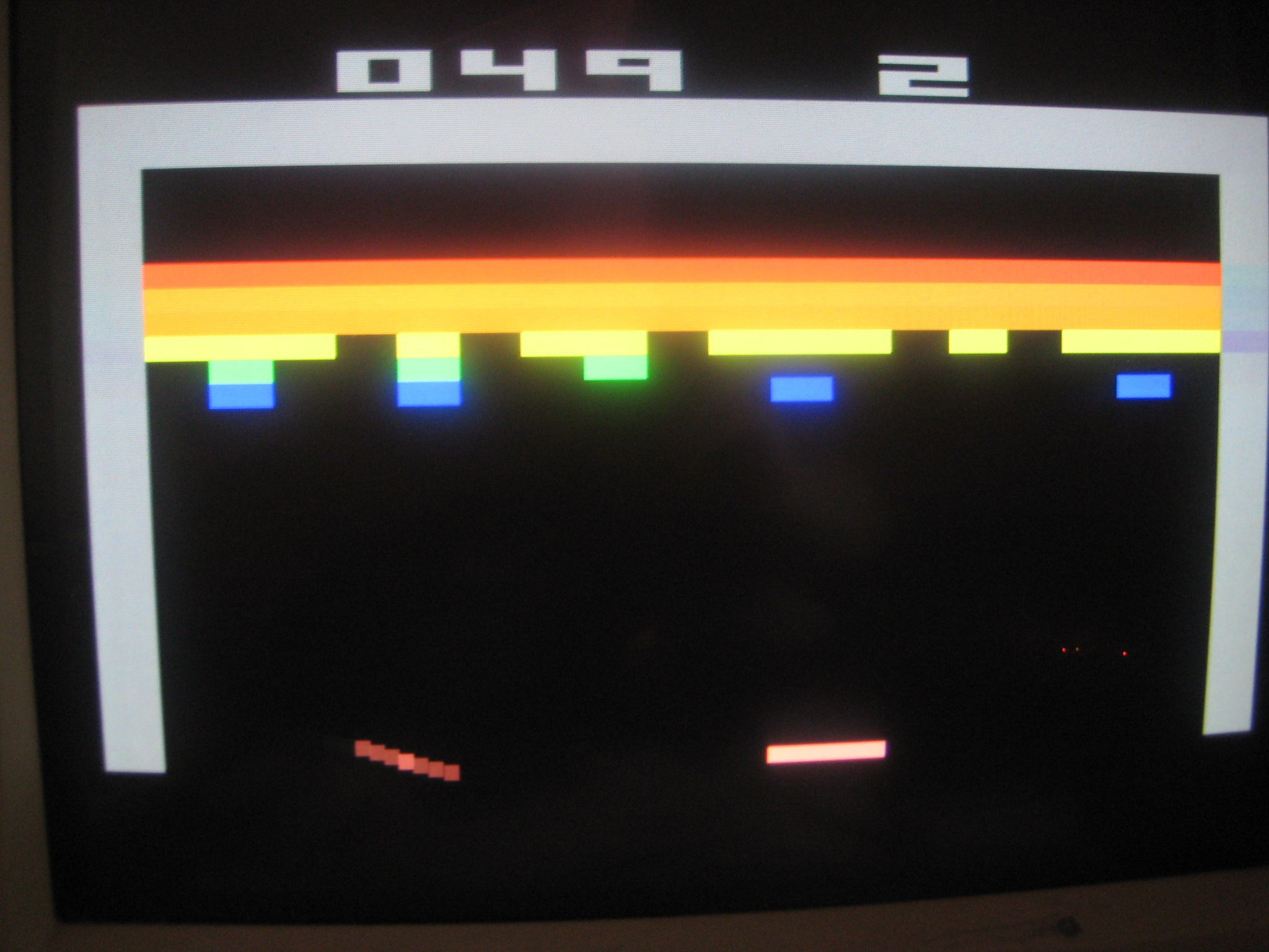
It turns out that the additional 5 rows of bricks really added to the complexity of the design. I found tons of problems with the collisions where they would work, but then at some certain points, the ball would fly through a brick instead of collide with it. My collision logic basically uses division to determine what brick row/column the ball was at when colliding with a brick. For example, to determine if the brick row that the ball is currently at, I do the following division: (ball_y - bricks_top) / brickHeight This is integer math, so the result would equal the brick row (0 to 5). The brick column check works the same way: (ball_x - wall_left_edge) / brickWidth Checking for a left or right brick edge collision used a modulus, so that if (ball_x % brickWidth == 0), the ball_x value would be such that the ball's x-position is at a left brick edge. All this seemed to be valid, but when I tried to synthesize to the FPGA, I was reminded of one critical thing with these FPGAs... all divisions must be be factors of 2. So my brickWidth (6) could not be used in the above divisions. When working with just one row of bricks, everything worked fine since I wasn't doing the division by brickHeight to determine the brick row - I was just hardcoding the brick row to be zero. Fortunately I found a provided core object in the Xilinx libraries that provides a Division module... otherwise I would have had to resize everyhing to look incorrectly or create my own digital division module. So after using this module I was able to get the ball moving again. Also in the process I discovered that some of the sizes were off. The ball and paddle heights were actually 4 instead of 3. And the paddle width was 16 instead of 18. So after about 1 full weekend of working on these collision issues, I was finally able to get all the bricks working with collisions. Check it out below. |
||||||||||||||||||||
|
||||||||||||||||||||
|
||||||||||||||||||||
| Another video! Breakout Graphics - Take 3 | ||||||||||||||||||||
|
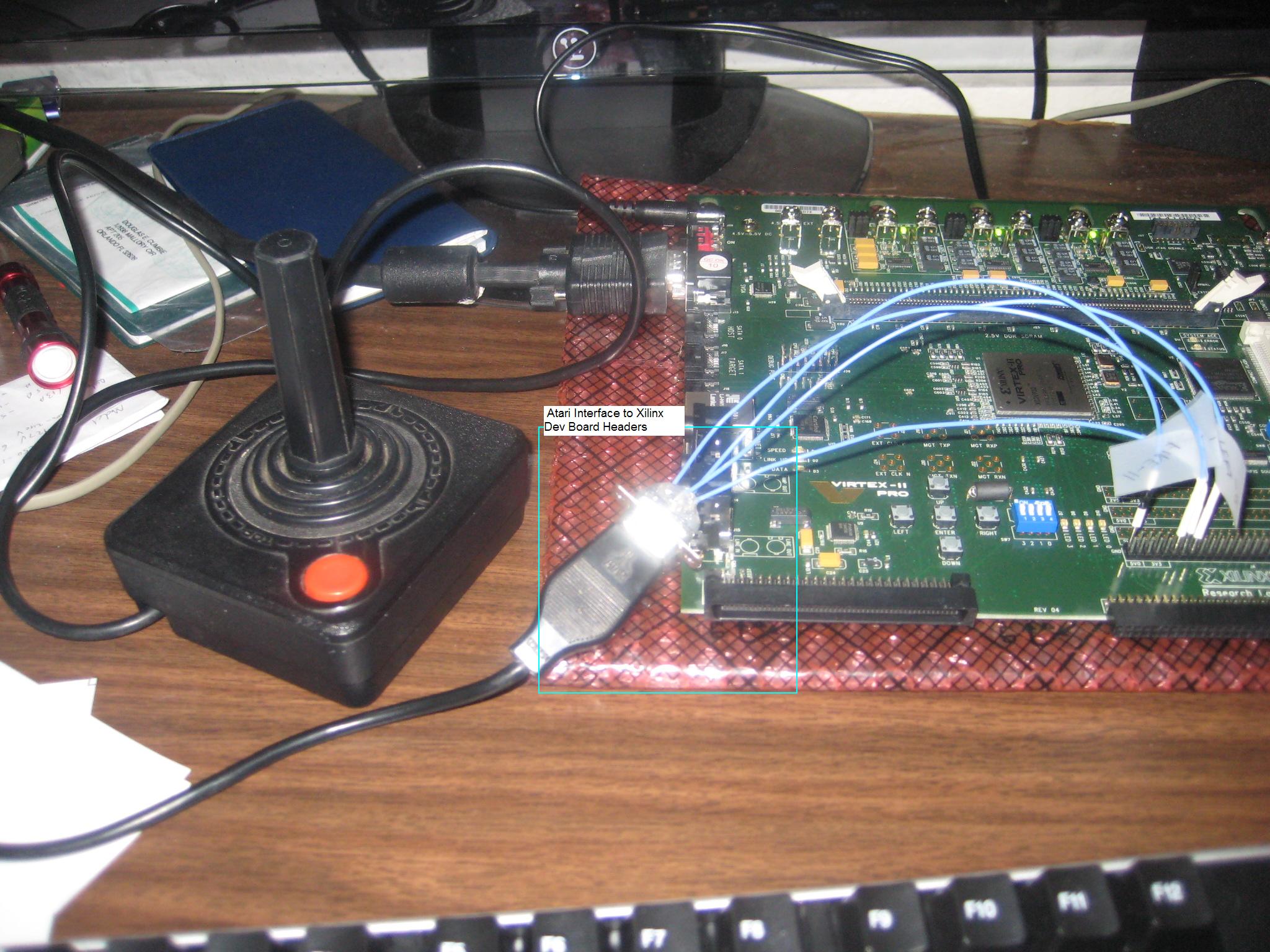
So the next phase of tasks consisted of getting the scoreboard up on the screen (showing the score and lives), working on altering the ball's slope at different collision points on the paddle, and maybe working on an Atari joystick module. I started with the joystick module. The Atari joystick is a simple device that basically contains switches for each of its direction inputs and fire button. When moving the joystick or pressing the fire button, a circuit is closed to ground. Atari Joystick Pin-outs:
The joystick's connector is a 9-pin D-sub female connector. I picked up a RS-232 male connector at Radio Shack and put together an adapter to interface the joystick to the Xilinx dev board. On the dev board there are 4 banks of general I/O pins. Some of these expansion headers were used to accept the joystick's inputs. The Xilinx board comes without the pins for these headers, so I had to puchase some (60-pin) and solder then to the board. Below is a pic of the interface: |
||||||||||||||||||||
|
||||||||||||||||||||
|
Since the inputs from the joystick are shorted to ground when pressed, I would only have to look for logic lows to determine an input. A quick Verilog test app proved that it really was that simple. So I created a module that took 3-inputs for Left, Right, and Fire joystick inputs and inverted them so that I could deal with positive logic. Replacing the keyboard interface with the new Joystick interface made the game a bit more fun. |
||||||||||||||||||||
|
The scoreboard would need to have a set of fonts (numerals 0 to 9) to work with. I added in some logic to the Verilog code to maintain a score (10-bit register) and the remaining lives (3-bit register). To display the score and lives I first worked out the font number's bitmaps on paper and then created a .COE file containing the binary data for each number (0 to 9). Each number font is a 16x14 pixel bitmap. For 0 to 9, I'd need a 16 bit wide x 140 deep ROM module to hold the fonts. I set it up so that each number had its own ROM to make it a bit easier to deal with. I added in some code to test if the lives number would show correctly. And it did, however then value initially was displayed backwards... but that was an easy things to correct. Displaying the 3-digit score involved a little extra work. The 10-bit internal score register provided for the 0-864 possible score. Since I only had numbers 0 to 9, I had to break up this value into it's hundreds, tens, and ones part to update each score digit. I added a module that did this by dividing up the current score value and returning the scores' hundreds, tens, and ones value. To test, I created a counter that would count up when the SW6 button was pressed on the Xilinx board. Below is a pic showing the score and lives displayed. |
||||||||||||||||||||
|
||||||||||||||||||||
|
I then integrated this score module into the game and it worked pretty nice. The last task involved modifying the slope of the ball's trajectory when it hit different points on the paddle. As is typical with many things, this turned out to be easier said than done. My logic was setup so that the ball's slope (delta_y/delta_x) would be regulated such that:
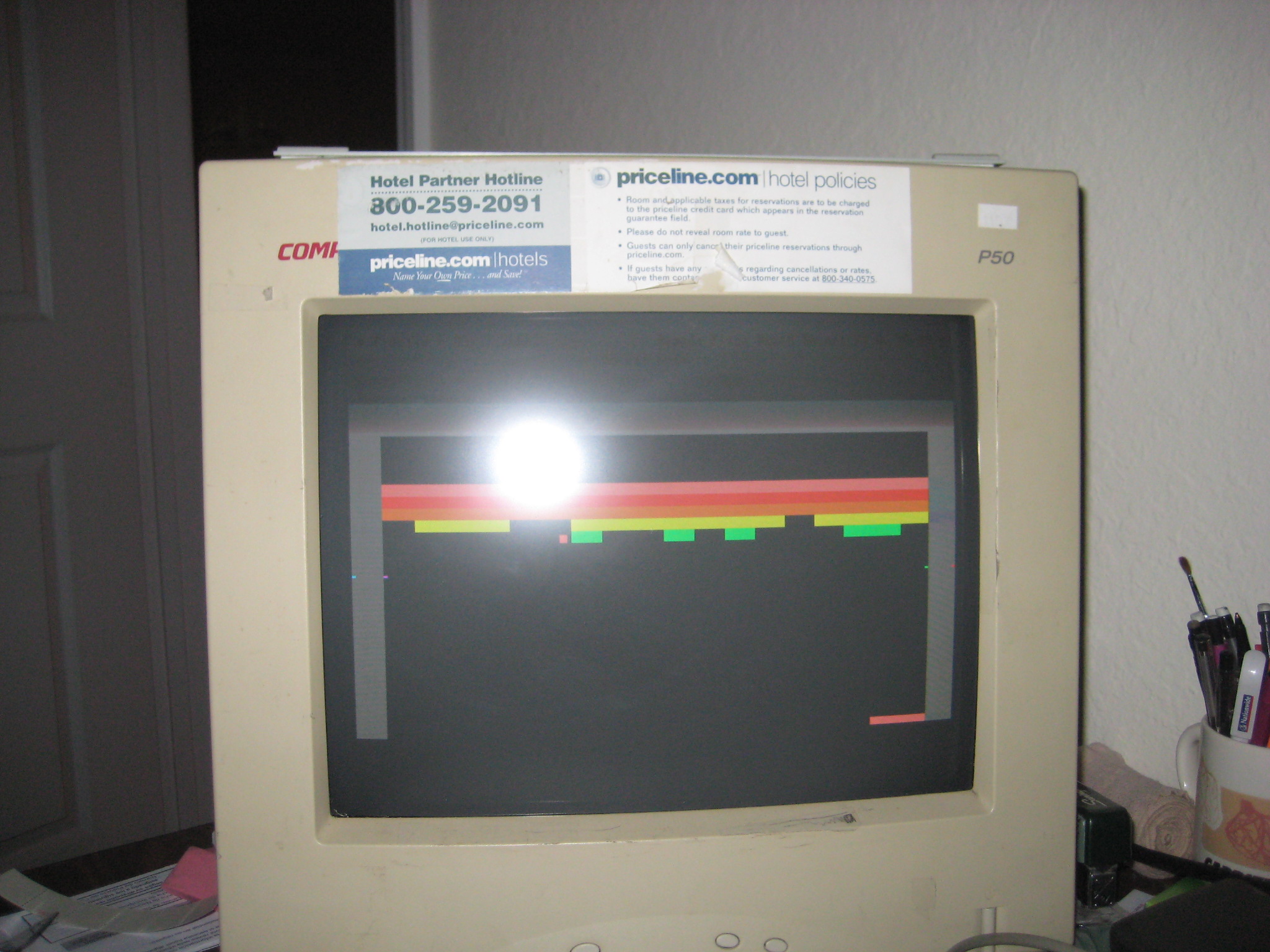
So to resolve this, I kept the logic for brick side-edge collisions, but for these collisions did not alter the brick-state register. So the ball can only destroy a brick by colliding with its top or bottom edge. This added a little more challenge to the game and removed the problems seen from the side-edge collisions. The end result was not perfect - sometime the ball seems to get stuck in between brick row and destroy more bricks than it should - but this barely has any real effect with the overall gameplay. Below are some screenshots of the final results along with some videos. |
||||||||||||||||||||
|
||||||||||||||||||||

|
||||||||||||||||||||
|
YouTube video showing the overall setup and use of FPGA Breakout: |
||||||||||||||||||||
| Video1: FPGA Breakout (1) | ||||||||||||||||||||
| Video2: FPGA Breakout (2) | ||||||||||||||||||||
| Final Report | ||||||||||||||||||||
| Final Presentation |